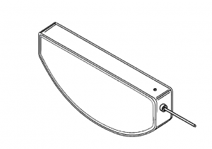
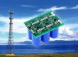
an anode pack housed within the casing and comprising more than one anode,pellets of anode active material electrically connected to each other by a bridge,
and a cathode comprised of cathode current collectors including major faces with cathode active material provided thereupon is described. The bridge, which spans
between sidewalls of the anode pellets, helps maintain them in a parallel alignment. The bridge is also a convenient location to connect the feedthrough wire that exits the casing through a glass-to-metal seal. The cathode current collectors are disposed between adjacent anode pellets and are electri cally connected to each other and to the casing. A feedthrough wire electrically connected to the anode pack extends outside the casing in electrical isolation there from. An electrolyte is
provided to activate the anode and the cathode.

reference standard
- MIL-STD-202, “Test Methods for Electronic and Electrical Components”
- MIL-STD-883, “Test Methods and Procedures for Microelectronic Devices”
| parameter | Specifications and Tolerances |
| Charging voltage (maximum voltage) | Maximum DC 238 V |
| electric capacity | 470μF±40μF |
| d-c leakage current | Maximum 155 μA |
| charging interval | Initial operating life (BOL): up to 16.5 seconds |
| energesis | Minimum 12.0 J |
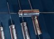
- High energy density, compact form factor for miniaturized ICD design
- Hermetically sealed tantalum construction, hermetic leakage tested
- Ultra-low DC leakage current (Low DCL), minimizes battery drain over service life
- Stable performance at 37°C body temperature, long design life (10+ years target)
- Biocompatible material package, implant-grade construction
- Available custom capacitance, voltage, footprint and termination options