Multilayer ceramic chip capacitor CCAF / MLCC for aerospace
◆Each batch is DPA, and 100% of the products are screened for temperature shock and high temperature load。
I dielectric:Resonant circuits, coupling circuits and circuits requiring low loss, high capacitance stability and high insulationresistance
II dielectric: Circuits with bypass, filter, low frequency coupling or low requirements for loss and capacitancestability
| 3, Part number sample | |||||||||||||||
| CCAF | 0805 | CG | 101 | J | 1H | 6 | |||||||||
| series | size code | temperature coefficient | Capacitance code | tolerance code | voltage code | failure rate class | |||||||||
| 6 failure rate class 6 / 5failure rate class 5 aerospace technology certification | |||||||||||||||
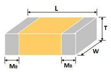
| size code(unit:mm) | |||||||||||||||
| outline | size | 0402 | 0603 | 0805 | 1210 | 1812 | |||||||||
 unit:mm unit:mm |
L | 1.00±0.10 | 1.60±0.15 | 2.00±0.30 | 3.20±0.40 | 4.50±0.50 | |||||||||
| W | 0.50±0.10 | 0.80±0.15 | 1.25±0.20 | 2.50±0.30 | 3.20±0.40 | ||||||||||
| T max | 0.60 | 1.00 | 1.50 | 2.80 | 3.50 | ||||||||||
| size | 2220 | 2225 | 3025 | / | / | ||||||||||
| L | 5.70±0.50 | 5.70±0.50 | 7.50±0.50 | / | / | ||||||||||
| W | 5.00±0.50 | 6.50±0.50 | 6.30±0.50 | / | / | ||||||||||
| T max | 5.10 | 5.10 | 5.00 | / | / | ||||||||||
| MB | 0.95±0.30 | 0.95±0.30 | 0.50±0.50 | / | / | ||||||||||
| temperature coeffient capacitance markmethod | |||||||||||||||
|
series |
temperature
coeffient/code |
Allow capacitance change | temperature range |
It is marked with three digits,The first two digits mark the effective value of the electrical capacity,The third digit mark the number of zeros after the valid value,unit pF,for exmaple:101=100pF(0.1nF) 103=10000pF(10nF) |
|||||||||||
| without UR | with UR | ||||||||||||||
|
CCAF |
COG/ CG BC/Z
BP/L |
0±30ppm/℃ | / | -55℃~125℃ | |||||||||||
| BX / O | ±15% | +15/-25% | -55℃~125℃ | ||||||||||||
| BR / Y | ±15% | +15/-40% | -55℃~125℃ | Capacitance tolerance | |||||||||||
| BY / M | ±15% | / | -55℃~125℃ |
I dielectric |
CR<10pF | B:±10pF | C:±0.25pF | ||||||||
| rated voltage | D:±0.5pF | / | |||||||||||||
| 0J 6.3V, 1A 10V, 1C 16V, 1D 20V, 1E 25V, 1H 50V, 1J 63V, 2A 100V, 3A 1000V…… |
CR≥10pF |
F:±1% | G:±2% | ||||||||||||
| termination | J:±5% | K:±10% | |||||||||||||
| Nickel Barrier | II dielectric | K:±10% | M:±20% | ||||||||||||
INTRODUCTION
Types of Dielectric Material and Capacitor
◆HIGH FREQUENCY TYPE: The capacitor of this kind dielectric material is considered as ClassⅠcapacitor,
including high frequency COG、COH capacitor and temperature compensating capacitor such as HG, LG, PH,
RH,SH, TH, UJ, SL. The electrical properties of COG、COH capacitor are the most stable one and change invariablly
with temperature, voltage and time. They are suited for applications where low-losses and high-stability are required,
HG,LG,PH,RH,SH,TH,UJ,SLcapacitor’s capacitance changes with temperature.They are suited for applications
where low-losses and temperature compensating circuits.
◆ X7R、X5R、X7S、X6S:X7R、X5R、X7S、X6S material is a kind of material has high dielectric constant. The capacitor
made of this kind material is considered as Class Ⅱ capacitor whose capacitance is higher than that of class Ⅰ.
These capacitors are classified as having a semi-stable temperature characteristic and used over a wide temperature
range, such in these kinds of circuits, DC-blocking, decoupling, bypassing, frequency discriminating etc.
◆ Y5V:The capacitor made of this kind of material is the highest dielectric constant of all ceramic capacitors. They are
used over a moderate temperature range in application where high capacitance is required because of its unstable
temperature coefficient, but where moderate losses and capacitance changes can be tolerated. Its capacitance and
dissipation factors are sensible to measuring conditions, such as temperature and voltage, etc.
◆ Z5U:The capacitor made of this kind of material is considered as ClassⅡ capacitor, whose temperature characteristic
is between that of X7R and Y5V. The capacitance of this kind of capacitor is unstable and sensible to temperature and
voltage. Ideally suited for bypassing and decoupling application circuits operating with low DC bias in the environment approaches to room temperature.