Capacitores eletrolíticos gerais ▏85 ℃ 2.000 ~ 3.000 horas ▏CAFB
85℃, 2000horas para Dia < 8milímetros, 3000horas Dia > 10milímetros
Standard series for general purpose
Replaces RC, RÉ & RH Series
ESPECIFICAÇÕES
| Item | Desempenho | |||||||||||||||||||||||||||||
| Temperatura operacional. | -40°C ~ +85°C | |||||||||||||||||||||||||||||
| Tolerância de capacitância | ± 20% (120Hz, 20° c) | |||||||||||||||||||||||||||||
|
Corrente de fuga (a 20ºC) |
Tensão nominal | < 100V | >100V | |||||||||||||||||||||||||||
| Tempo | Depois 2 minutos | Depois 5 minutos | ||||||||||||||||||||||||||||
|
Corrente de fuga |
I = 0,01CV ou 3 (µA)
o que for maior |
cv < 1000
Eu = 0,03CV + 15(µA) |
cv > 1000
I = 0.02CV + 25(µA) |
|||||||||||||||||||||||||||
| Where C = rated capacitance in F. V = rated DC working volatage in V. | ||||||||||||||||||||||||||||||
| Tensão nominal | 6.3 | 10 | 16 | 25 | 35 | 50 | 63 | 100 | 160 | 200 | 250 | 350 | 400 | 450 | ||||||||||||||||
| Dissipation Factor Tanδ
a 120Hz, 20° c |
Tan δ (máx.) | 0.23 | 0.20 | 0.16 | 0.14 | 0.12 | 0.10 | 0.09 | 0.08 | 0.12 | 0.14 | 0.17 | 0.20 | 0.25 | 0.25 | |||||||||||||||
| When the capacitance exceeds 1000μF, 0.02 shall be added for every 1000μF increase. | ||||||||||||||||||||||||||||||
|
Características de baixa temperatura (a 120Hz) |
A relação de impedância não deve exceder os valores indicados na tabela abaixo. | |||||||||||||||||||||||||||||
| Tensão nominal | 6.3 | 10 | 16 | 25 | 35 | 50 | 63 | 100 | 160 | 200 | 250 | 350 | 400 | 550 | ||||||||||||||||
|
Impedance Radio |
Z(-25° c) | φD<16 | 6 | 4 | 3 | 3 | 2 | 2 | 2 | 2 |
3 |
6 |
8 |
12 |
14 |
16 |
||||||||||||||
| /Z(+20° c) | φD>16 | 8 | 6 | 4 | 4 | 3 | 3 | 3 | 3 | |||||||||||||||||||||
| Z(-40° c) | φD<16 | 10 | 8 | 6 | 6 | 4 | 3 | 3 | 3 | 4 | 8 | 10 | 10 | 10 | 10 | |||||||||||||||
| /Z(+20° c) | φD>16 | 18 | 16 | 12 | 10 | 8 | 8 | 6 | 6 | |||||||||||||||||||||
|
Load Life test at 20°C (after rated voltage is applied at 85°C for 2000 |
Tempo de teste | 2000horas(3000hrs for φ D > 10milímetros) |
Shelf Life at 20°C after exposure to 85 para 1000 hours with |
Tempo de teste | 1000horas | |||||||||||||||||||||||||
| Mudança de capacitância | Dentro de < ±20% of initial value | Mudança de capacitância | Dentro de < ±20% of initial value | |||||||||||||||||||||||||||
| Fator de Dissipação | Menor que 200% of specific value | Fator de Dissipação | Menor que 200% of specific value | |||||||||||||||||||||||||||
| / 3000 horas) | Corrente de fuga | Dentro do valor especificado | no voltage | Corrente de fuga | Dentro do valor especificado | |||||||||||||||||||||||||
|
Corrente Ondulada & Multiplicadores de frequência |
Frequência. (Hz)
Boné. (µF) |
60
(50) |
120 |
500 |
1K |
10K
acima |
||||||||||||||||||||||||
| Sob 100 | 0.70 | 1.00 | 1.30 | 1.40 | 1.50 | |||||||||||||||||||||||||
| 100 para 1000 | 0.75 | 1.00 | 1.20 | 1.30 | 1.35 | |||||||||||||||||||||||||
| 1000 e acima | 0.80 | 1.00 | 1.10 | 1.12 | 1.15 | |||||||||||||||||||||||||
| Corrente Ondulada & Multiplicadores de temperatura | Temperatura (° c) | Sob 50 | 70 | 85 | ||||||||||||||||||||||||||
| Mutipliers | 1.78 | 1.4 | 1.00 | |||||||||||||||||||||||||||
| Padrões | Satisfaz a Característica W de JIS C 5141 | |||||||||||||||||||||||||||||
DIMENSÃO & CORRENTE DE ONDULAÇÃO PERMITIDA
Corrente Ondulada :mA/rms at 120Hz, 85° c
| V.DC
eu F Código |
6.3V (JO) | 10V (1UM) | 16V (1C) | 25V (1E) | 35V (1V) | 50V (1H) | 63V (1J.) | 100V (2UM) | |||||||||
| ΦDxL | mA | ΦD xL | mA | ΦDxL | mA | ΦDxL | mA | ΦDxL | mA | ΦDxL | mA | ΦDxL | mA | ΦDxL | mA | ||
| 0.1 | 0R1 | 5 x 11 | 1.5 | 5 x 11 | 3 | 5 x 11 | 3 | ||||||||||
| 0.2 | R22 | 5 x 11 | 3.5 | 5 x 11 | 5 | 5 x 11 | 5.8 | ||||||||||
| 0.3 | R33 | 5 x 11 | 5 | 5 x 11 | 8 | 5 x 11 | 8.8 | ||||||||||
| 0.5 | R47 | 5 x 11 | 7 | 5 x 11 | 10 | 5 x 11 | 12 | ||||||||||
| 1.0 | 10 | 5 x 11 | 15 | 5 x 11 | 17 | 5 x 11 | 22 | ||||||||||
| 2.2 | 2R2 | 5 x 11 | 29 | 5 x 11 | 28 | 5 x 11 | 33 | ||||||||||
| 3.3 | 3R3 | 5 x 11 | 35 | 5 x 11 | 34 | 5 x 11 | 40 | ||||||||||
| 4.7 | 4R7 | 5 x 11 | 31 | 5 x 11 | 40 | 5 x 11 | 42 | 5 x 11 | 45 | 5 x 11 | 48 | ||||||
| 10 | 100 | 5 x 11 | 49 | 5 x 11 | 54 | 5 x 11 | 58 | 5 x 11 | 65 | 5 x 11 | 70 | 5 x 11
6.3 x 11 |
59
80 |
||||
| 22 | 220 | 5 x 11 | 70 | 5 x 11 | 75 | 5 x 11 | 80 | 5 x 11 | 87 | 5 x 11 | 95 | 6.3 x 11 | 115 | 6.3 x 11
8 x 11.5 |
115
135 |
||
| 33 | 330 | 5 x 11 | 72 | 5 x 11 | 84 | 5 x 11 | 90 | 5 x 11 | 97 | 5 x 11
6.3 x 11 |
108
115 |
5 x 11
6.3 x 11 |
136
163 |
6.3 x 11
8 x 11.5 |
140
340 |
8 x 11.5
10 x 16 |
145
195 |
| 47 | 470 | 5 x 11 | 90 | 5 x 11 | 100 | 5 x 11 | 110 | 5 x 11 | 115 | 5 x 11
6.3 x 11 |
130
145 |
6.3 x 11 | 165 | 6.3 x 11
8 x 11.5 |
170
397 |
10 x 13
10 x 16 |
235
255 |
DIMENSÃO & CORRENTE DE ONDULAÇÃO PERMITIDA
Corrente Ondulada :mA/rms at 120Hz, 85° c
* = Plano (não ventilado) tampão de borracha.
Other units are made with raised (ventilado) tampão de borracha
.
EXEMPLO DE NÚMERO DE PEÇA
CAFB 471 M 1C BK 100 125
ESPAÇAMENTO E DIÂMETRO DO CHUMBO
| φD | 5 | 6.3 | 8 | 10 | 13 | 16 | 18 | 22 | 25 |
| P | 2.0 | 2.5 | 3.5 | 5.0 | 5.0 | 7.5 | 7.5 | 10 | 12.5 |
| φd | 0.5 | 0.6 | 0.8 | 1.0 | |||||
| um | 1.0 | 1.5 | 2.0 | ||||||
| b | 0.5 | ||||||||
HOW TO MAKE UM PAPEL NÚMERO

- Série:CAFB
- Capacitância: Rated capacitance in µF is represented by a three digit number. The first two digits are the significant figures of the nominalcapacitance and the third digit indicates the number of zeros following these The decimal point is represented by the capital letter R. Please refer to the following example.
μF 0.1 0.47 1 4.7 10 47 100 470 1000 4700 10000 Número da peça 0R1 R47 010 4R7 100 470 101 471 102 472 103 - Tolerância: (20% ISTypical)
Código K M T C Tolerância + 10% + 20% + 50% /-10% + 100% /-10% - Tensão nominal: Voltage in volts (V) is represented by a two digit code showing the rated working voltage indicated asfollows:
Tensão (WV) 6.3 10 16 25 35 40 50 63 80 100 160 200 250 350 400 450 Código 0J. 1UM 1C 1E 1V 1G 1H 1J. 1K 2UM 2C 2D 2E 2V 2G 2C - Lead Forming &Package
Código Lead Description Embalagem BC Bending Cut Bulk Packing BK Straight Lead Bulk Packing CC Lead Cutting Bulk Packing FC Lead Forming & Cutting Bulk Packing FF Lead Forming Bulk Packing SC Snap-in & Cutting Bulk Packing SD Cathode Lead Beading Bulk Packing SF Snap-in, Forming & Cutting Bulk Packing sobre Straight Lead Fita & Munição TA Lead Forming Fita & Munição SR Straight Lead Fita & Carretel TR Lead Forming Fita & Carretel
- CanSize
Diâmetro (milímetros)x10 & Length (milímetros)x10. Can Size 063110, represents 6.3mm diameter by 11mm length.
- Wire and SleeveType*
= (Omit) Liderar (Pb) Free Wire & PVC Sleeve
`P = Lead (Pb) Free Wire & PET Sleeve
*Observação: All standard RFE Aluminum Electrolytic Capacitors are Lead (Pb) free and RoHS compliant. PET sleeve is available for those companies
that also require PVC free product.
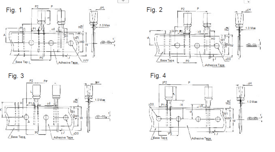
LEADED TAPING & PACKAGING SPECIFICATIONS
Taping Specification for Radial Lead Type
| Embalagem | TA,TR (Figo. 1) | sobre, SR (Figo. 2, 3, 4) | ||||||||||||||||||
| eu | L ≤ 7mm | L ≥ 7mm | L ≤ 7mm | L ≥ 7mm | ||||||||||||||||
| fD
Symbol |
f 3 |
f 4 |
f 5 |
f6.3 |
f 8 |
f 5 |
f 6.3 |
f 8 |
f 3 |
f 4 |
f 5 |
f 6.3 |
f 8 |
f 5 |
f 6.3 |
f 8 |
Tol. |
f 10 |
f 13 |
Tol. |
| fd | 0.4 | 0.45 | 0.5 | 0.5 | 0.5 | 0.5 | 0.5 | 0.6 | 0.4 | 0.45 | 0.45 | 0.45 | 0.45 | 0.5 | 0.5 | 0.6 | ± 0.05 | 0.6 | 0.6 | ± 0.05 |
| F | 5.0 | 5.0 | 5.0 | 5.0 | 5.0 | 5.0 | 5.0 | 5.0 | 2.5 | 2.5 | 2.5 | 2.5 | 3.5 | 2.5 | 2.5 | 3.5 | -0.2/+0.8 | 5.0 | 5.0 | -0.2/+0.8 |
| P | 12.7 | 12.7 | 12.7 | 12.7 | 12.7 | 12.7 | 12.7 | 12.7 | 12.7 | 12.7 | 12.7 | 12.7 | 12.7 | 12.7 | 12.7 | 12.7 | ± 1.0 | 12.7 | 25.4 | ± 1.0 |
| P0 | 12.7 | 12.7 | 12.7 | 12.7 | 12.7 | 12.7 | 12.7 | 12.7 | 12.7 | 12.7 | 12.7 | 12.7 | 12.7 | 12.7 | 12.7 | 12.7 | ± 0.2 | 12.7 | 12.7 | ± 0.30 |
| P2 | 6.35 | 6.35 | 6.35 | 6.35 | 6.35 | 6.35 | 6.35 | 6.35 | 6.35 | 6.35 | 6.35 | 6.35 | 6.35 | 6.35 | 6.35 | 6.35 | ± 1.0 | 6.35 | 6.35 | ± 1.3 |
| P1 | 3.85 | 3.85 | 3.85 | 3.85 | 3.85 | 3.85 | 3.85 | 3.85 | 5.1 | 5.1 | 5.1 | 5.1 | 4.6 | 5.1 | 5.1 | 4.6 | ± 0.5 | 3.85 | 3.85 | ± 0.7 |
| H | 17.5 | 17.5 | 17.5 | 17.5 | 17.5 | 18.5 | 18.5 | 20.0 | 17.5 | 17.5 | 17.5 | 17.5 | 17.5 | 18.5 | 18.5 | 18.5 | ± 0.75 | 18.5 | 18.5 | ± 0.75 |
| H0 | 16.0 | 16.0 | 16.0 | 16.0 | 16.0 | 16.0 | 16.0 | 16.0 | — | — | — | — | — | — | — | — | ± 0.5 | — | — | ± 0.5 |
| C | 18.0 | 18.0 | 18.0 | 18.0 | 18.0 | 18.0 | 18.0 | 18.0 | 18.0 | 18.0 | 18.0 | 18.0 | 18.0 | 18.0 | 18.0 | 18.0 | ± 0.5 | 18.0 | 18.0 | ± 0.5 |
| W0 | 12.0 | 12.0 | 12.0 | 12.0 | 12.0 | 12.0 | 12.0 | 12.0 | 12.0 | 12.0 | 12.0 | 12.0 | 12.0 | 12.0 | 12.0 | 12.0 | Mínimo | 12.0 | 12.0 | Mínimo. |
| W1 | 9.0 | 9.0 | 9.0 | 9.0 | 9.0 | 9.0 | 9.0 | 9.0 | 9.0 | 9.0 | 9.0 | 9.0 | 9.0 | 9.0 | 9.0 | 9.0 | ± 0.5 | 9.0 | 9.0 | ± 0.5 |
| W2 | 1.5 | 1.5 | 1.5 | 1.5 | 1.5 | 1.5 | 1.5 | 1.5 | 1.5 | 1.5 | 1.5 | 1.5 | 1.5 | 1.5 | 1.5 | 1.5 | Máx.. | 1.5 | 1.5 | Máx.. |
| f D0 | 4.0 | 4.0 | 4.0 | 4.0 | 4.0 | 4.0 | 4.0 | 4.0 | 4.0 | 4.0 | 4.0 | 4.0 | 4.0 | 4.0 | 4.0 | 4.0 | ± 0.2 | 4.0 | 4.0 | ± 0.2 |
| t | 0.7 | 0.7 | 0.7 | 0.7 | 0.7 | 0.7 | 0.7 | 0.7 | 0.7 | 0.7 | 0.7 | 0.7 | 0.7 | 0.7 | 0.7 | 0.7 | ± 0.2 | 0.7 | 0.7 | ± 0.2 |
| H | 0 | 0 | 0 | 0 | 0 | 0 | 0 | 0 | 0 | 0 | 0 | 0 | 0 | 0 | 0 | 0 | ± 1.0 | 0 | 0 | ± 1.0 |
| l | 1.0 | 1.0 | 1.0 | 1.0 | 1.0 | 1.0 | 1.0 | 1.0 | 1.0 | 1.0 | 1.0 | 1.0 | 1.0 | 1.0 | 1.0 | 1.0 | Máx.. | 1.0 | 1.0 | Máx.. |
| UM | 11 | 11 | 11 | 11 | 11 | 11 | 11 | 11 | 11 | 11 | 11 | 11 | 11 | 11 | 11 | 11 | Máx.. | 11 | 11 | Máx.. |
| Figo. Não. | 1 | 1 | 1 | 1 | 1 | 1 | 1 | 1 | 2 | 2 | 2 | 3 | 3 | 2 | 3 | 3 | 3 | 3,4 | ||
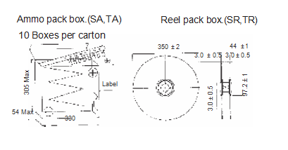
Packaging Quantity
| D | 3 | 4 | 5 | 6.3 | 8 | 10 | 13 |
| TA, sobre | 3000 | 2000 | 2000 | 2000 | 1000 | 500 | 250 |
| TR,SR | 3000 | 1500 | 1200 | 1000 | 800 | 500 | 500 |
NOTES:
- The above quantities are typical. Quantities may
- The component will be oriented on the tape so that the positive lead is leading or the negative lead is leading, depending on the customer’srequest
CARACTERÍSTICAS
◆ 2000hrs(3000hrs for φ D > 10milímetros) assured
◆ SlimType
◆ Compatível com Rohs